Industrial Network Engineering
Balluff Industrial Networking, From the Sensor to the PLC
Balluff Industrial Network Engineering covers the hardware between your field devices and the controller: network blocks that connect directly to the industrial Ethernet network, IO-Link modules that bring sensors and actuators onto those blocks, and the couplers, wireless links and switches that extend the network to places a cable can’t reach. Because the components come from one manufacturer, the network blocks, IO-Link devices and on-machine cabling are designed to work together.
Manuauto is an authorized Balluff distributor in Canada and the U.S. We help machine builders and integrators choose the right protocol, port layout and I/O mix for each machine.
The Building Blocks of a Balluff Machine Network
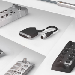
Network Blocks
What it doesConnect field devices directly to EtherNet/IP, PROFINET, EtherCAT or CC-Link IE Field. Many models are IO-Link masters.
When you need itEvery on-machine I/O layout starts here
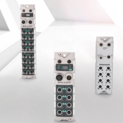
IO-Link Sensor/Actuator Hubs
What it doesExtend one IO-Link master port to up to 16 discrete sensors and actuators
When you need itStations with many simple switching devices
Universal IO-Link Interfaces
What it doesBring any device with up to 16 inputs/outputs onto IO-Link
When you need itPumps, signal lights, control panels and valve terminals without their own IO-Link port
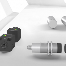
Inductive Couplers
What it doesTransmit power and signals contactlessly across a small air gap
When you need itTool changers and rotary indexing tables
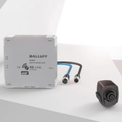
IO-Link Wireless
What it doesReplace the IO-Link cable with a radio link
When you need itMoving or continuously rotating equipment
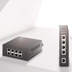
Industrial Switches
What it doesIP67 Ethernet switches for on-machine networks
When you need itDistributing the network without a control cabinet
Moving I/O Out of the Cabinet and Onto the Machine
In a conventional layout, every sensor and valve is wired back to terminal blocks and I/O cards in the control cabinet. With IP67 network blocks and hubs, the I/O moves to the station where the devices are, and pre-assembled cordsets replace individual wire terminations. For machine builders, that changes more than the wiring:
Smaller cabinets, fewer wiring errors. Fewer terminal blocks and I/O cards free up panel space, and keyed, pre-assembled connectors remove most of the opportunities for a miswired point.
Machines built in modules. Each module carries its own network block, so it can be built and tested on its own, shipped separately and reconnected on site with one network cable and one power cable.
Troubleshooting at the station. Status LEDs on every port show the state of each device where it is mounted, so a technician doesn’t have to trace wires back to the cabinet.
One detail is often missed during installation: the IP67 rating only holds when every port is sealed. Fit protective caps on unused M12 sockets, especially in washdown and coolant areas.
Choosing a Network Block: Start With the Protocol
The network block has to speak the same protocol as your PLC, so that decision comes first. The usual pairings in North American plants are:
| Protocol | Typical controller platforms | Balluff range |
|---|---|---|
| EtherNet/IP | Rockwell Automation (Allen-Bradley) | Network blocks for EtherNet/IP |
| PROFINET | Siemens | Network blocks for PROFINET |
| EtherCAT | Beckhoff and PC-based motion control | Network blocks for EtherCAT |
| CC-Link IE Field / Field Basic | Mitsubishi Electric | CC-Link IE Field·CC-Link IE Field Basic |
With the protocol fixed, four more details decide the exact model:
IO-Link master or plain I/O. An IO-Link master accepts IO-Link sensors, hubs and interfaces as well as standard switching devices. A digital I/O block handles switching signals only, which is enough for simple stations but closes the door on device diagnostics.
Number and class of ports. Count today’s devices and leave room for additions. Where valves or other actuators need power that can be cut separately from the sensors, choose Class B ports. Our IO-Link hub page explains how to plan that power budget.
Power connector. Blocks are supplied through 7/8" or M12 L-coded power connectors. L-coded M12 carries a high current in a smaller footprint, which helps on crowded machines.
Network topology and housing. Models with two Ethernet ports and an integrated switch can be daisy-chained along a machine without a separate switch. Metal housings suit weld cells and high-vibration areas.
What IO-Link Adds Beyond the On/Off Signal
Connecting devices through an IO-Link master turns each sensor from a simple switch into a source of data. In daily operation, that shows up in five ways:
From Your I/O List to a Complete Machine Network
Send us your PLC platform and I/O list, and we’ll recommend the network blocks, hubs and cabling for the machine.
Frequently Asked Questions
Can an IO-Link sensor work without an IO-Link master?
Yes. Connected to a standard digital input, an IO-Link sensor runs in SIO (standard I/O) mode and behaves like a conventional switching sensor. You lose the measured values, diagnostics and remote parameter access until it is connected to a master port.
What cable does an IO-Link connection need?
A standard unshielded 3-, 4- or 5-wire sensor cable with M8 or M12 connectors, up to 20 m between the master port and the device. No shielded or fieldbus cable is required, which keeps cabling costs at the level of conventional sensor wiring.
What is an IODD file, and where do I get it?
The IODD (IO Device Description) is an XML file that describes an IO-Link device’s parameters, process data and diagnostics. You import it into the master’s configuration tool or engineering software to set the device up. IODDs are available from the manufacturer’s website and from IODDfinder, the IO-Link community’s central database.
Should I use an inductive coupler or IO-Link Wireless?
An inductive coupler transmits both power and signals across a small air gap between two aligned faces, so it suits positions where a tool or fixture docks at a fixed point, such as a robot tool changer or rotary indexing table. IO-Link Wireless replaces the data cable over a longer range and suits equipment that moves freely or rotates continuously, but each wireless device still needs its own power supply.